Tunnel and Reservoir Plan
History
The Metropolitan Water Reclamation District of Greater Chicago (MWRDGC) has a combined sewer system, in which both storm sewer and household sewer are diverted to water reclamation stations. The Combined Sewer Area within the MWRDGC totals 375 square miles, encompassing all or part of 52 communities, including the City of Chicago. Prior to 1972, wet weather flow from these combined sewers was diverted to waterways, which was the acceptable practice in those times. Overflows to the waterways were occurring approximately 100 days per year, causing substatial waterway pollution.
Note: click on pictures to get an enlargement.
Overview
 The Tunnel and Reservoir Plan (TARP) was adopted by the Metropolitan Water Reclamation District of Greater Chicago (MWRDGC) in 1972 to
solve the combined sewer overflow (CSO) pollution and flooding problems in the Chicago-land area served by combined sewers. TARP consists of constructing 109 miles of deep tunnel, bored in rock and lined with concrete. Currently, 93 out of the 109 miles of planned Phase 1 tunnels are in operation and the remaining tunnels are under construction. The tunnels range from 9-33 ft in diameter and are located 200 to 350 ft below ground.
The system also includes reservoirs, drop shafts, connecting structures, pumping stations, and other appurtenances for the capture and storage of CSOs and for conveying the 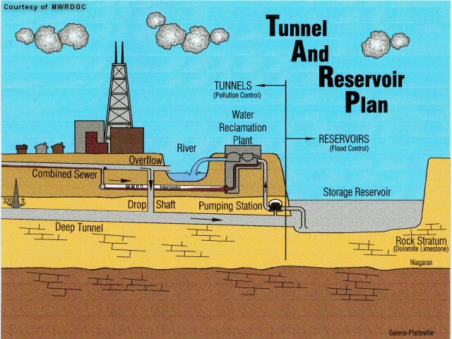 stored CSOs to water reclamation plants for treatment. All 450 CSOs in the 375 square mile service area are diverted to the deep tunnel system. Reservoirs are located at the downstream ends of the tunnels to provide additional storage capacity for CSOs, and consist of the Thornton Reservoir (24,200 Acre-Feet), the McCook Reservoir (32,000 Acre-Feet), and the O’Hare Reservoir (1,050 Acre-Feet). The total cost of TARP when completed will be approximately $3.1 billion.
Computer simulations and modeling studies were originally performed during the conceptual stages of TARP Phase I tunnel design. As portions of the system came online, computers were used to model operation of the tunnels under actual storm events as well as to predict operations when the TARP Phase II reservoirs are on-line. Although the existing models were used to simulate actual storm events, they were based on design, rather than as-built specifications for the system and are now outdated.
The MWRDGC now desires to develop a new, updated and enhanced computer model for each TARP system, to allow real-time control of the TARP systems1. Whereas the
original models were used to test the hydraulics of structures and explain certain phenomena that occurred in the early stages of tunnel operation, a new real-time flow model will be used to optimize operation of the system as actually constructed, and to determine constraints in the system, identify physical changes that may be needed to improve performance, and allow “what-if” analyses to be performed for potential storm scenarios and facility revisions.
The research conducted at the Ven Te Chow Hydrosystems Laboratory at the University of Illinois builds upon research of Prof. Ben Yen with respect to the conveyance and capacity analysis. Prof. 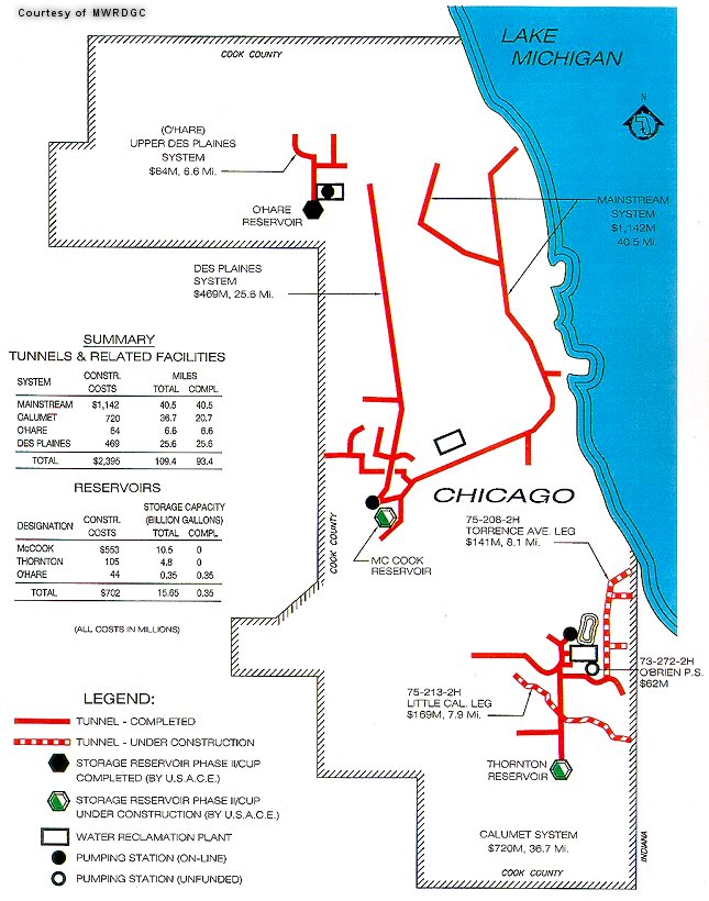 Yen’s research developed a new method to determine open channel flow capacity under backwater effects. A hydraulic performance graph was first developed summarizing the subcritical flow backwater profile conditions for all the feasible upstream and downstream water levels and discharges. The channel capacity was determined accordingly as the marginal condition of just-bankfull stage without spilling overbank at the most critical point in the channel. The TARP research will build upon this by extending the principles to flow in closed conduits.
1 The major TARP systems include the Calumet, Des Plaines, and Mainstream system tunnels and structures and the Thornton Transitional Reservoir, as well as the future Thornton Composite and McCook reservoirs.
Research and Modeling
The initial phase of research will be to develop the models for the Calumet TARP system. This system, when completed, represents about one-third of the total length of tunnels in the system and serves about one-fourth of the combined- sewer area of greater Chicago. This system also contains a wide variety of hydraulic structures and possible hydraulic conditions. Developing the models and analysis tools for the Calumet TARP system will help to ensure that models have all the required capability prior to developing them for the larger Mainstream and Des Plaines system.
Development of these models for the each major component of the TARP system is subdivided into phases. The first phase is to develop a Physical Inventory and to develop a Hydraulic Assessment of the system. The second phase is to develop and calibrate a Hydraulic Transient Model for the system. The third phase will utilize the models developed in the first two phases for an Assessment of the Operational Instrumentation and Methodologies and for Specific Issue Investigations. The investigations included in the third phase will require more detailed Hydrologic Modeling of the contributing drainage area. Although Kiefer and Associates (1976) performed a Hydrologic Assessment as part of the preliminary design of the Calumet system, this analysis was limited to peak discharges and therefore does not provide the inflow hydrographs that will be needed for the Assessment of the Operational Methodologies. Furthermore over thirty years have passed since the most recent data included in this analysis. As a result, the Hydrologic Modeling should be re-done to provide up-to-date information that can be synthesized with the Hydraulic Assessment and Modeling to perform the real-time modeling and “what-if” analysis that are the overarching goal of this work.
Phase One
The Physical Inventory will provide a digital description of the hydraulic performance and related physical geometry of the TARP system. This provides a framework that will facilitate development of the hydraulic models by consolidating all of the tunnel and structure geometry data required by the models. This inventory also will facilitate updating the model to reflect changes to components of the system or to reflect improved hydraulic descriptions of components of the system.
The Hydraulic Assessment will include stage-storage curves for the tunnels and dropshafts and an assessment of the hydraulic capacity of each component of the Calumet TARP system. The assessment of the hydraulic capacity will summarize the flow discharge characteristics of each component/structure for the range of possible operating conditions. As a result, results from the Hydraulic Assessment can be used to determine the controlling feature at each location in a manner that reflects interactions among the components of the system.
Phase Two
 The discharge characteristics of many of the structures are expected to be quite complex and their behavior will not be described by tables of discharge coefficients for standard structures. For example, many of the dropshafts were designed as un-gated structures and sluice gates were added at a later time. The hydraulic characteristics of the dropshaft and associated structures will control the inflow to the tunnels, yet the behavior of these structures has never been examined. Because of the complex interactions among inlets, sluice gates, tide gates, the drop shaft, and the connecting tunnels, it is expected that three-dimensional hydrodynamic modeling will be required to assess the discharge characteristics of the as-built structures. Computational Fluid Dynamics (CFD) will be used for the modeling to assess the discharge characteristics for selected, representative hydraulic structures. It is anticipated that many of the relations developed to describe discharge characteristics for representative structures from the Calumet TARP system will apply to structures from the Mainstream and Des Plaines systems, potentially reducing the level of CFD analysis required for these systems.
The Hydraulic Transient Modeling done in the second phase will provide the foundation for the development of what will constitute the overarching goal of this project: a real-time flow model for the operation of the TARP system. This phase will result in a calibrated hydraulic model that is capable of simulating the range of possible flows, from gravity to surcharged flows to hydraulic transients.
2 The connecting structure diverts flow from the outfall sewer to the drop shaft. Sluice gates are provided at the larger drop shafts to control inflow, if necessary. Drop shafts were designed to convey flow to the deep tunnel and allow release of displaced air from the tunnel. The TARP system includes over 250 drop shafts, ranging in diameter from 4 to 25 feet. There are over 400 connecting structures.
Phase Three
The Assessment of the Operational Instrumentation and Methodologies done in the third phase will utilize the models developed in the first two phases to assess the effectiveness of the existing operational plans, to identify possible improvements to these plans through revisions to the methodology or set points currently utilized and to develop potential operating plans in conjunction with operation of the reservoirs. The existing equipment and instrumentation utilized for operation and monitoring of the system will be reviewed to determine optimum locations and any deficiencies or needs with respect to the equipment currently utilized. Any known alternative equipment or technology which has the potential to enhance the operation or reliability of the system will be investigated for potential use and reported on.
The Specific Issue Investigations will use the data and models from the first two phases to assess and investigate several specific items with respect to the actual or potential operation of each tunnel system.
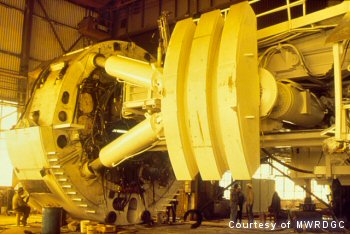
27 ft. Tunnel Boring Machine used on one of the contracts.
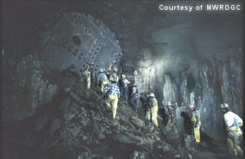
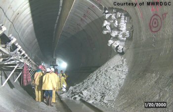
Holing out of branch tunnel (17 ft. into 32 ft.). Tunnel is unlined – the smooth face is a result of the Tunnel Boring Machine.
Holing out – Tunnel Boring Machine penetrating through terminal construction shaft where it would be disassembled and removed.
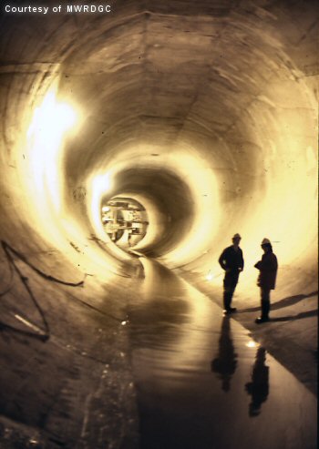
Finished tunnel with concrete lining to reduce infiltration/exfiltration
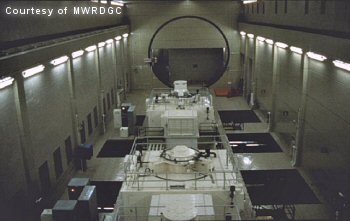
The Mainstream Pumping Station is located 350 feet below ground and is used to pump the Mainstream and Des Plaines tunnel systems to the 1200 mgd Surface Water Reclamation Plant.